I took part in an internship at animation studio as a software engineer. I won’t go into details for confidentiality reasons, but it was good experience. Everyone was kind and supportive to me. That’s why my blog update was delayed.
By the way, I got the results back from a license examination called “CG Engineer Certification Test” by CG-ARTS. To my joy, I was able to pass the test with full marks.
For fun, I went Tokyo, Osaka and Nagoya and meet friends in this summer.
I have to get down to work and write a master’s thesis, so I will update this blog at a slow pace.
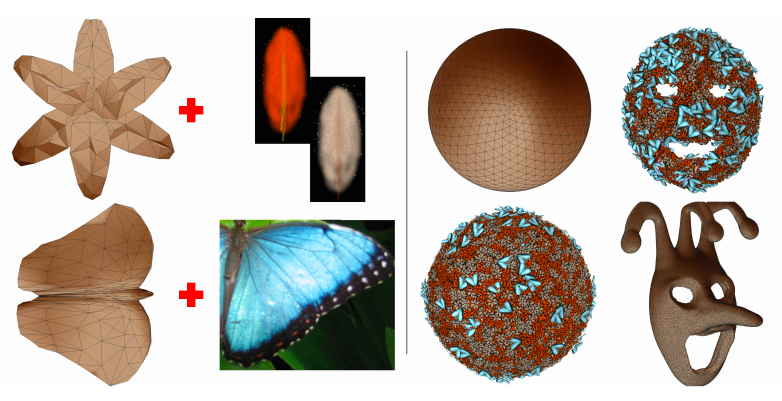
This work propose the method of deforming an agglomeration of component elements (named CompEls) in real time as below.
from Temporally Coherent Sculpture of Composite Objects page2
There are some exiting techniques to represent a surface composed small 3D objects, for example, stipples and texture bombing. However, they are time consuming and not intended to be used in real time.
Novelty of the study
Realtime sculpting and visualize CompEls using techniques below.
Empirical description by uniform meshes
Because the physically accurate interaction of components is too complex to compute in realtime, this method uses empirical description. The system focus on the outer layers of the shape represented as the quasi-uniform meshes. The system detect that the surface expand by the emergence of new sampling anchors.
quasi-uniform meshes is defined by threshold d and t below. d: the maximum distance between two sampling point t: the minimum distance below which the edge collapse Check “Freestyle: Sculpting meshed with self-adaptive topology” for details.
CompEls are placed according to samples on the triangle of the mesh. Each one has 3parameters, the barycentric coordinate, depth level and orientation relative to the triangle.
Temporal coherence and continuity by controlling depth level
In this work, visual continuity is maintained. CompEls newly added are generated in deep layers and then appear to the surface from inside. And extra CompEls are first pushed toward the deeper layer before disappearing.
CompEl movement accompanying edge modification
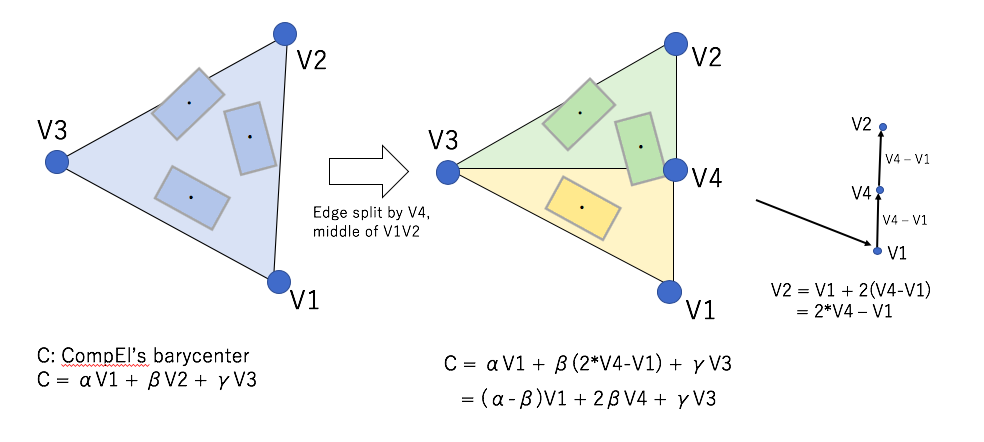
Edge split
If the length of edge become longer than threshold d, the edge will be split. the barycenters of CompEls don’t move but be assigned new face.
change of the ComEl’s barycenter in Edge split processing
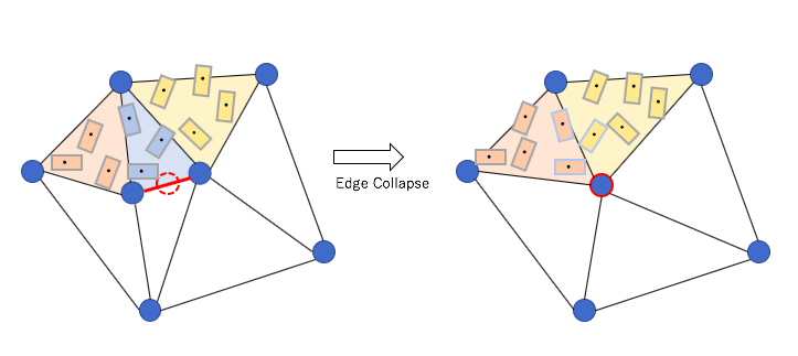
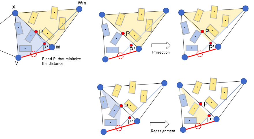
Edge collapse
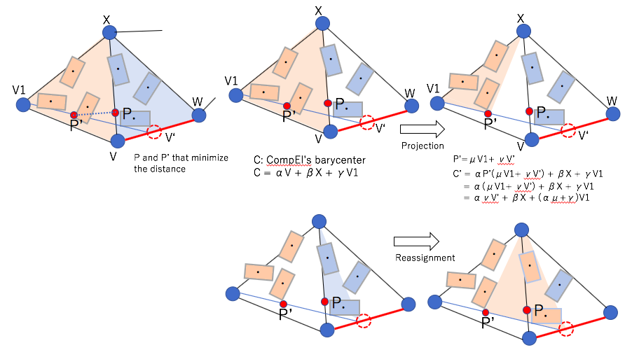
If the length of edge become shorter than threshold t, the edge will collapse and all faces involved are reshaped. And each barycenters of CompEls are projected new faces.
What edge collapse ise.g.1 left side of deleted face change of the ComEl’s barycenter in Edge collapsee.g. 2 right side of deleted face
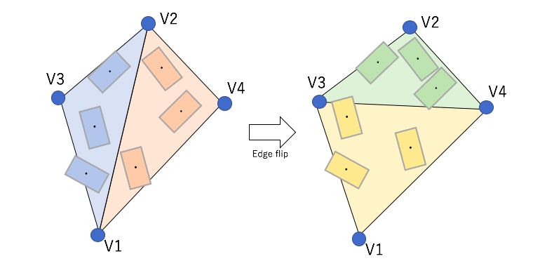
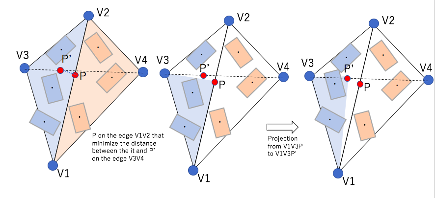
Edge flip
Edge flip is one of the ways of maintaining the distance of vertices without splitting or deleting edges.
what edge flip ischange of the ComEl’s barycenter in edge flip
Change in topological genus
Change in topological genus is to reconnect vertices to maintain distance of correctly without moving the coordinates of them.
Techniques in rendering
Variability
CompEls are displayed using instance based modeling. Visual variability of each instance is acquired by using different texture and using low frequency noise.
Back CompEl Culling
If there is no back face culling function in graphic card, the system replaces CompEls on back face to the out of the view by comparing the eye direction to the normal vector of the quasi-uniform mesh which is closest to the CompEl’s barycenter.
CompEl squish
CompEl squish is the way of visual intersection prevention. By squeezing CompLes at a constant scale in the direction perpendicular to the canvas, CompEls are prevented to overlap in appearance.
Result
Please refer to the original paper to see some resulting images.
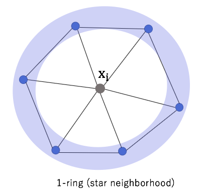
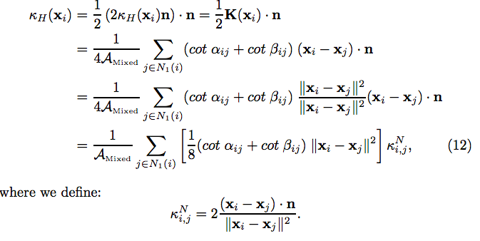
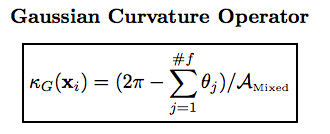
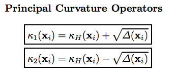
Deriving first and second order operators at the vertices of a mesh using the 1-ring(star neighborhood). In other words, providing the way to extend the definition of curvature from continuous surfaces to discrete meshes.
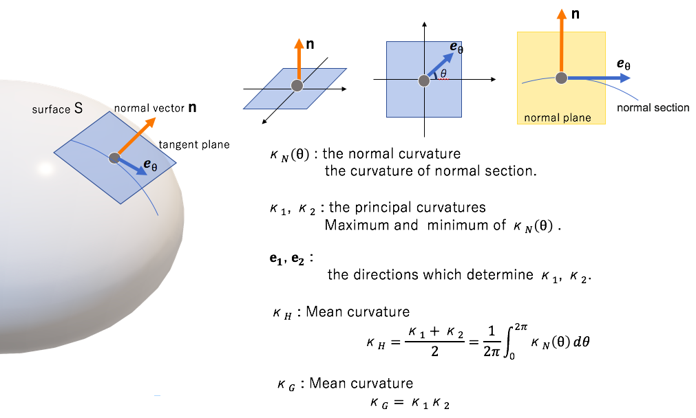
Definitions of the curvature in continuous surface
The normal curvature and related notions are defined as follows.
@Nako 2019
Approximation
The average calculation is restricted to be within the immediately neighboring triangles referred as the 1-ring.
@Nako 2019
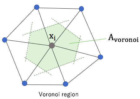
The voronoi region is used as small area around point xi.
@Nako 2019
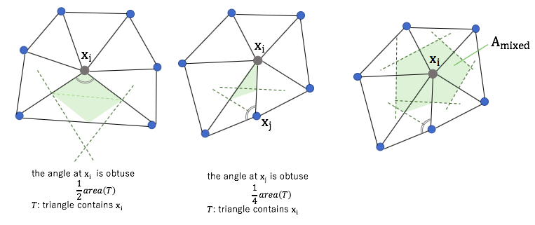
However, the formula for the Voronoi finite-volume area does not hold in the presence of obtuse angles. So mixed area is used in the actual calculation.
@Nako 2019
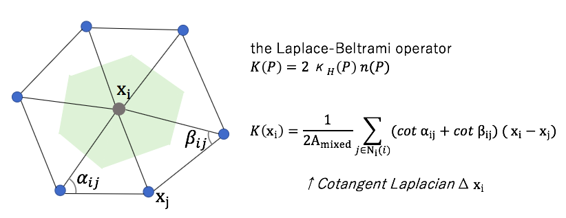
The Laplace-Beltrami operator K is computed. The Laplace-Beltrami operator (the mean curvature normal operator) is a generalization of the Laplacian from flat spaces to manifolds.
@Nako 2019
Derivation
from “Discrete Differential-Geometry Operators for Triangulated 2-Manifolds”from “Discrete Differential-Geometry Operators for Triangulated 2-Manifolds”from “Discrete Differential-Geometry Operators for Triangulated 2-Manifolds”
Vegetation is often seen in Digital Terrain Model(DTM), but it takes too much effort for artist to model. There are some techniques to improve the efficiency in vegetation synthesis, L-systems, the space colonization algorithm and so on. However they require point cloud, multiple photographs or various parameter setting.
Novelty of the study
This work proposes a pipeline to reconstruct and render plausible trees from a single photograph.
Method of crown reconstruction from the photo.
Envelope mesh synthesis
Color synthesis
Relief synthesis
Radial distance map
Branches and leaves generation
1, Envelope mesh synthesis
Get tree silhouette pixels S using 8-connectivity from the photo.
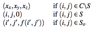
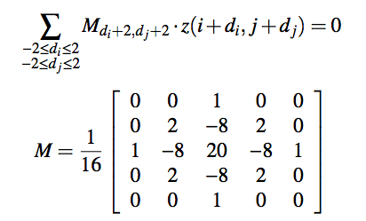
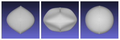
Fix the silhouette points on the z = 0 plane and maintain their tangents of the point (i, j, 0) to be f(i, j). Then get crown mesh C as height map. To realize this constraint, define the outer silhouette S_o as the set of pixels outside C but adjacent to a silhouette pixel.
Crown C is determined by minimizing the thin-plate energy defined by a biharmonic equation inside the crown C. In actual calculation, each of unknown(x, y, z) are figured out using equation below. The matrix M is bilaplacian filter.
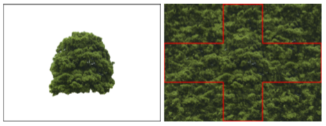
Create color map from the photo by using the texture synthesis algorithm of Image texture tools(P. Harrison, 2005). Then create cube map from the synthesized texture.
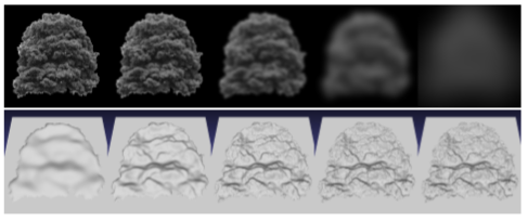
3, Relief synthesis
The next step is estimation of relief (depth) from luminance of the photo. At first, the luminance is normalized in the [0,1] range. The system computes a blur pyramid of the luminance. Lower levels (low-frequencies) will have larger weights, while higher levels are used to add small fine details to the relief.
Create radial distance map(RDM) that stores distance from the center of the crown to the surface, and set values by projection of the cube map of relief.
5, Branches and leaves generation
Branches are created by the Space Colonization Algorithm in the crown. And leaves are represented as set of billboards for simplicity.
Rendering
There are 2 ways of rendering the tree.
Fragment-based relief mapping which is for distant trees
Billboard cloud with an RGBA texture drawing leaves and branches which is for close trees
Check the output trees generated by this method in the original paper.
Today I’ve read the paper “PointNet: Deep Learning on Point Sets for 3D Classification and Segmentation” by Charles R. Qi, Hao Su, Kaichun Mo, Leonidas J. Guibas.
What is PointNet?
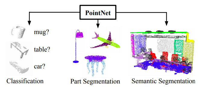
PointNet is a neural network that directly consumes point cloud, unordered point set. While the architecture is simple, it provides an approach to object classification, part segmentation and semantic segmentation with a good performance.
Novelty of the study
While typical CNN requires volume data, like voxel, or a collection of images, these representations cause a lack of detail while the sampling process. So PointNet take point clouds directly as an input. The input is (x, y, z) coordinates of N points, which are given in no particular order.
Applications of PointNet
PointNet can perform well in 3 tasks below.
3D Object Classification
3D Object Part Segmentation
Semantic Segmentation in Scene
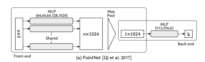
from PointNet: Deep Learning on Point Sets for 3D Classification and Segmentation page1
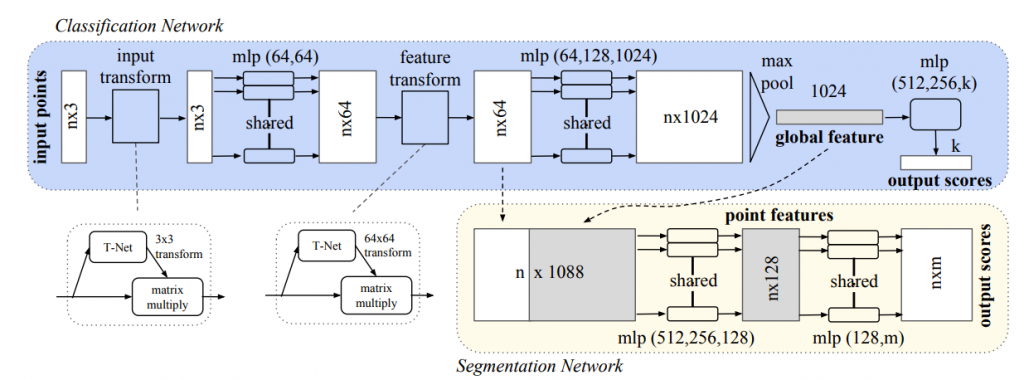
Architecture
overall
Each one of input points is input to the same mlp(Multilayer perceptron), and features are extracted.
from PointNet: Deep Learning on Point Sets for 3D Classification and Segmentation page3
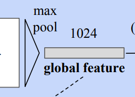
Symmetric function
As a strategy to make a model invariant to input permutation, a symmetric function is used. A symmetric function is the function whose value is the same no matter the order of the given n arguments, n points in this case. In this model, the symmetric function is mlp network and max-pooling which aggregates point features.
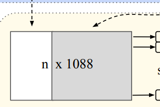
Local and global information aggregation
Both the local and global information is required for point segmentation. PointNet concatenate the global feature with point features and extract new per point features.
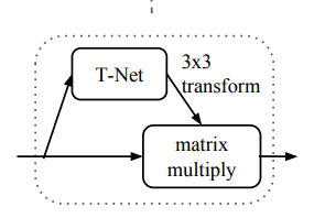
Invariance to the transformation
The semantic labeling need to be invariant to geometric transformations of shapes. PointNet predicts an affine transformation matrix by a mini-network (T-Net). The mini-network is composed by basic modules of feature extraction, max pooling and fully connected layers.
Visualization
They visualize critical point sets and upper-bound shapes in this paper. It enables us to summarize an input point cloud by a sparse set of key points.
It is one of the methods of modeling in which user selects and arrange components into the completed object. For example, a chair model is composed of components of back, seat, foot and handrail.
In incremental interactive assembly modeling, user chooses a complementary component one by one to add it into the partial assembly. It is desirable for such modeling systems to suggest applicable parts as complementary components so that they require two key technical components, retrieval and placement.
The problem is that it takes too much time and effort to label components and create dataset for component suggestion.
This work proposes a method of weakly-supervised component suggestions for 3D modeling.
Novelty of the study
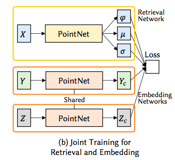
This system has 3 neural net, Retrieval Network, Embedding Network and Placement network.
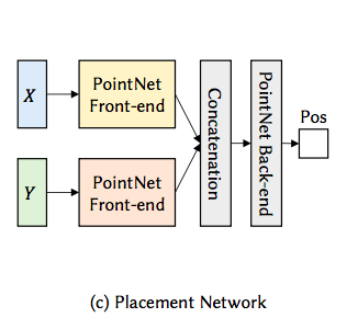
Retrieval Network is trained to take partial assembly X and output a probability distribution as a weighted gaussian distribution over the embedded space for each complementary component. Embedding Network is trained to take part geometry Y and maps it to low-dimensional vector. Retrieval Network and Embedding Network are trained jointly. Placement network is trained to take X and Y and predict 3D coordinates, strictly translation of each complementary component.
Each architecture contains PointNet which takes 3D unordered points as input and classify into k class as output.
PointNet from Sung, Minhyuk; Su, H. 2017.ComplementMe: Weakly-Supervised Component Suggestions for 3D Modeling. p4
φ is weight, μ is mean and σ is standard deviation of Gaussian in the figure below.
Retrieval Network, Embedding Network from Sung, Minhyuk; Su, H. 2017.ComplementMe: Weakly-Supervised Component Suggestions for 3D Modeling. p4Placement Network from Sung, Minhyuk; Su, H. 2017.ComplementMe: Weakly-Supervised Component Suggestions for 3D Modeling. p4
Future work
Because this method randomly sample points over the surface of the input shape, larger components sometimes have bigger influences than small essential components.
I’m too foolish to delete my database for this blog! And my backup data was outdated. So I created new one that looks like the template of before one.
In this blog, I’ll write topics of programming, CGI software, and technical terms. Sometimes they contain film, music and Indian curry or pancake (they are my favorites).
Anyway, the first thing to do is to enable automatic data-backup.
I was too foolish that I deleted my database for this blog! And my backup data was outdated. So I created new one that looks like the template of before one.
In this blog, I’ll write topics of programming, CGI software, and technical terms. Sometimes they contain film, music and Indian curry or pancake (they are my favorites).
Anyway, the first thing to do is to enable automatic data-backup.
Open Tools -> Options and Check “” in Environment -> International Settings. If the language to use is in the list, click it and restart Visual Studio. If not, language pack should be installed.
Language pack installation
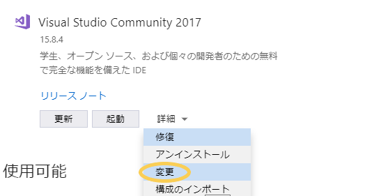
You need Visual Studio Installer. Open your Visual Studio installer or find a installer of the version you use now from https://visualstudio.microsoft.com/downloads/ . (In my case, the language of installer is Japanese)
Click “Modify”
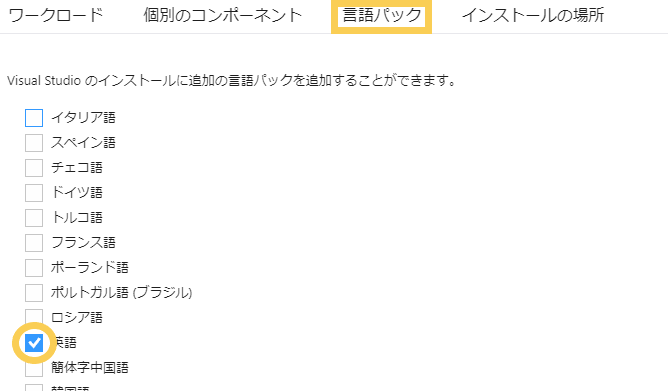
Open “Language packs” tab and select language.
Click Modify button at the right bottom of the window.
Language pack is added to the International Settings.